| Conventional Fire Alarm Control System :Conventional Fire Alarm Control Panel |
| |
|
|
General
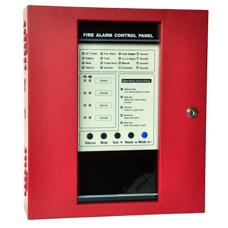
Conventional Fire Alarm Control Panel with four Zones
Key Specifications/Special Features
|
- Four Style B (Class B) Initiating Device Circuits (IDCs).
- All zones accept two-wire smoke detectors and any normally-open contact devices.
- One built-in, Style Y (Class B) Notification Appliance (Signal) Circuits (NACs).
- Alarm, Trouble and Supervisory, Form-C relays standard.
- 24-volt operation.
- Resettable four-wire smoke detector power @ 500 mA.
- Non-resettable power @ 500 mA.
- One-man walk-test programmable for silent or audible test.
- Disable/Enable control per IDC.
- Reverse polarity protection.
|
|
Specifications
AC Power
90-270 VAC, 50 Hz, 2.3 amps
Wire size: minimum #14 AWG (2.0 mm2) with 600V insulation
Battery (lead acid only)
Maximum Charging Circuit: Normal Flat Charge—27.6V @ 0.8 amp
Maximum Charger Capacity: 18 Amp Hour batter
Sound Output Device Circuits
General Alarm Zones 1 through 16
Operation: All zones Class B
Normal Operating Voltage: Nominal 24 VDC (ripple = 100 mV maximum)
Alarm Current: 15 mA threshold
Short Circuit Current: 42 mA maximum
Maximum Loop Resistance: 100 ohms
End-of-Line Resistor: 4.7K, ½ watt
Detector Loop Current is sufficient to ensure operation of two alarmed detectors per zone
Standby Current: 7.26 mA
Three Relays Output
Relay contact rating: 2.0 amps @ 30 VDC (resistive), 2.0 amps @ 30 VAC (resistive)
Nonresettable 24 VDC Power
Maximum ripple voltage: 10 mVRMS Operating Voltage nominal 24 volts
Total DC current available from this output is up to 500 mA
Recommended maximum Standby current is 150 mA