1. GENERAL DESCRIPTION
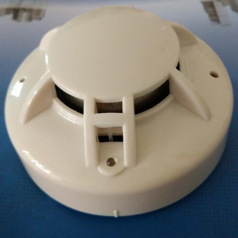
The smoke detector is photo-electronic detector uses a state of-the-art optical sensing chamber. This detector is designed to provide open area protection and to be used with most security alarm control panel. The LED on each detector flash every 5-6 seconds indicating that power is applied and the detector is working properly. The LED
latch on in alarm , will be off when a trouble condition exists indicating that the detector sensitivity is outside the listed limit. Smoke&heat detector combine a photo electronic sensing chamber and a temperature heat detector.
Test function (optional): When press the key on each detector the LED will be latch on, the sounder will be on and the relay will be output. In alarm: The detector can be restore to normal automatically when the ambient smoke or temperature below the alarm value (default).·The alarm can be reset only by a momentary power interruption(optional).
2. SPECIFICATIONS
Operating Voltage Range: 9 to 28 VDC Volts Non-polarized
Standby Current: ≤200µA
Maximum Alarm Current (LED on): ≤45mA
Alarm Relay Contact Ratings: 1A@ 24V DC
OperatingHumidityRange:≤95%RH(40°C±2°C)Relative Humidity,Non-condensing
Operating Temperature Range: -10°C to 50°C (14°F to 122°F)
Smoke Alarm Sensitivity: 0.15~0.3dB/m(with smoke sensor)
TemperatureAlarmSensitivity: 57°C (135°F)(withheatsensor)
Heatalarmclass: A2R (withheatsensor)
Sounder >80dB.(Optional)
Height: 55 mm installed in Base
Diameter: 103 mm
3. INSTALLATION
NOTE: All wiring must conform to applicable local codes, ordinances, and regulations.
INSTALL THE DETECTOR BASE
1. Open area smoke or heat detectors are intended for mounting on a ceiling or a wall in accordance with the fire
standard in your country.
2. Attach mounting base to ceiling or wall. The base of the detector can be mounted directly onto an electrical
junction box such as an octagonal (75mm, 90mm or 100mm), a round (75mm), or a square (100mm) box without using any type of mechanical adapter. See
Figure 1.
3. Position all wires flat against terminals, and fasten the wires on the terminals, See Figure 1.
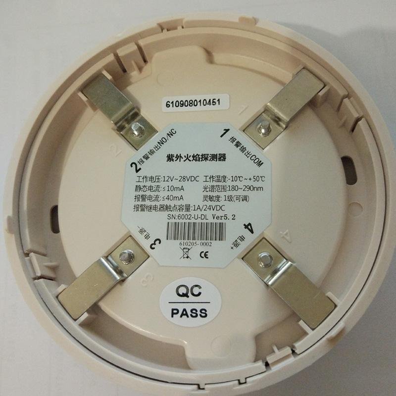
4. Terminals function description:
Terminal 1: Relay Output -COM
Terminal 2: Relay Output – NO/NC (default NO)
Terminal 3: DC Power –
Terminal 4: DC Power +(9V-28VDC)